The core of MTP/MPO fiber?assembly lies in its connector—MTP/MPO connector. MTP/MPO connector factory terminated assembly can house 6 to 72 fibers, with 12-fiber and 24-fiber arrays being the most common. MTP/MPO connector is available in a male version (with pins) or a female version (without pins). The pins ensure that the fronts of the connectors are exactly aligned on contact and that the endfaces of the fibers are not offset. There are guide grooves (keys) on the top side of the factory terminated MTP/MPO connector, which ensures that the adapter holds the connector with the correct ends aligned with each other. The push-pull design of MTP/MPO connector facilitates easier insertion and removal, making it a breeze when using with QSFP+ transceiver modules in 40/100G network.
What is MTP Modules and Harnesses?
An obvious benefit to deploying a MTP-based optical network is its flexibility to transmit both serial and parallel signals. MTP to duplex connector transition devices such as modules and harnesses are plugged into the MTP trunk assemblies for serial communication. MTP Modules are typically used in lower-portcount break-out applications such as in server cabinets. MTP harnesses provide a significant increase in cabling density and find value in high port count break-out situations such as SAN Directors . The built-in modularity of the solution provides flexibility to easily configure and reconfigure the cabling infrastructure to meet current and future networking requirements. MTP harnesses and modules can be exchanged or completely removed from the backbone network to quickly adapt to data center MACs.
MTP Modules in Data Centers
MTP modules typically are placed in a housing located in the cabinet rack unit space. Here the MTP trunk cable is plugged into the back of the module. Duplex patch cords are plugged into the front of the module and routed to system equipment ports. Integrating the MTP modules cabling solution into the data center cabinet can enhance the deployment and operation of the data center cabling infrastructure. As shown in the figure below, integrating the MTP modules into the cabinet vertical manager space maximizes the rack unit space available for data center electronics. MTP modules are moved to the cabinet sides where they snap into brackets placed between the cabinet frame and side panel. Properly engineered solutions will allow MTP modules to be aligned with low-port-count system equipment placed within the cabinet rack unit space to best facilitate patch cord routing.
MTP Harnesses in Data Centers
MTP harnesses are plugged into the backbone MTP trunk assemblies through an MTP adapter panel. The MTP adapter panel is placed in a housing that is also typically located in the cabinet rack unit space. MTP to LC 12-fiber break-out harnesses plug into the front of the adapter panels and are routed over to the director line cards where the LC duplex ends are plugged into the line card ports. These MTP harnesses are pre-engineered to a precise length with strict tolerances to minimize slack, while a small outside diameter allows for easy routing without preferential bend concerns. With a pre-engineered cabling management, not only is installation simplified, but the time required for SAN design and documentation is greatly reduced with port mapping architecture inherent to the design.
What is MTP/MPO Connectors?
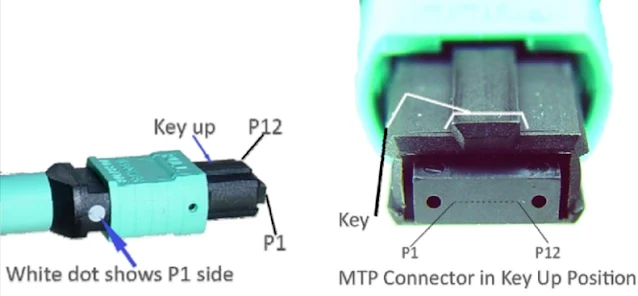
Before explaining the polarity, it is important to learn about the structure of MTP/MPO connector first. Each MTP connector has a key on one side of the connector body. When the key sits on top, this is referred to as the key up position. In this orientation, each of the fiber holes in the connector is numbered in sequence from left to right. We will refer to these connector holes as positions, or P1, P2, etc.?Each connector is additionally marked with a white dot on the connector body to designate the position 1 side of the connector when it is plugged in.
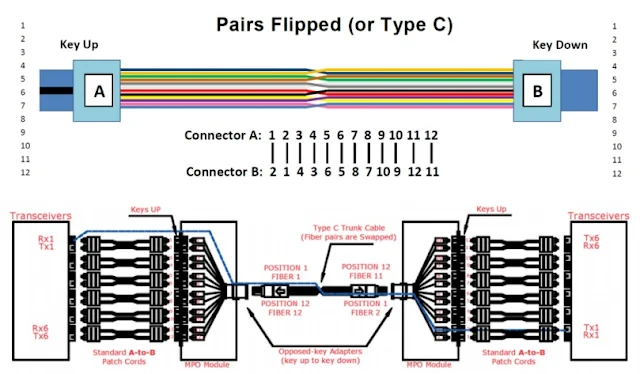
Since the MTP connectors can either key up and key down, there are two types of MPO adapters.


Post a Comment